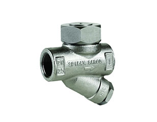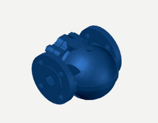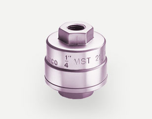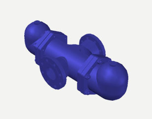
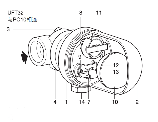
The UFT32 is a sealed stainless steel ball float steam trap designed for continuous, uninterrupted discharge of condensate from process equipment. Because the float chamber is welded closed rather than bolted, there is no body gasket to renew, no joint to re-torque and no leak path to develop in service – a decisive advantage where access for maintenance is difficult or where a shutdown is expensive.
It is a mechanical trap: a stainless steel float follows the condensate level and modulates the discharge valve in proportion to the load. Steam is held back until it has condensed, so the trap passes condensate at steam temperature, keeps the steam space flooded with dry steam and stays quiet in operation.
Design and construction
The body and cover are welded into a single sealed capsule, so the pressure boundary has no bolted joint. Float, lever and valve plug are stainless steel; the discharge orifice is sized to the duty. The trap discharges continuously rather than in batches, which avoids the water hammer and noise associated with intermittent traps and keeps the heat transfer surface of the equipment fully wetted.
Key features
- Sealed welded construction – no body gasket, no re-torquing, no joint leaks
- Continuous condensate discharge keeps process equipment at full heat transfer
- Stainless steel body and internals for clean steam, process and corrosive condensate
- Quiet operation – no cyclic opening and closing, no water hammer
- Works across the full load range without losing steam at part load
- Compact, lightweight capsule that suits skid-mounted and packaged plant
Selection and sizing
Size the UFT32 on the condensate load at the trap, not on the pipe size. Take the load in kg/h, the steam pressure upstream and the pressure downstream (back pressure from the return main, lift and any after-cooler), then confirm the differential pressure against the orifice capacity. For a jacketed vessel or heat exchanger running at 4.5 to 10 bar g with a condensate load of 200 to 800 kg/h, a DN15 to DN25 UFT32 is normally adequate. Where the condensate must be lifted, add a pump trap rather than a larger float trap.
Installation and maintenance
Fit the trap below the equipment drain point with a strainer upstream and a sight glass downstream so discharge can be verified. Allow a straight run into the trap and avoid lifting the condensate before the trap. On clean steam duty, specify the appropriate surface finish and install so the chamber drains fully. Sealed traps are not dismantled in service: replace the capsule when the orifice or float is worn, and keep a spare on site.
Options and spare parts
Supplied as a complete sealed unit; spare capsules, floats and discharge orifices are available against model and size. Insulation jackets, drain cocks and non-return arrangements can be specified with the order.