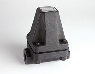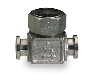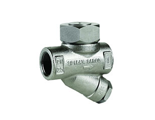
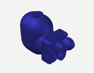
The FT14HC is the high capacity version of the FT14 ball float steam trap. It uses the same float-operated, continuously modulating principle, but with a larger discharge capacity in the same face-to-face length – the practical answer when a standard float trap of the line size would be marginal on a large condensate load.
Typical duties are heat exchangers, jacketed pans, calandrias and steam mains where condensate arrives in large, steady quantities. Because discharge is continuous and proportional to load, the trap holds the condensate at steam temperature and keeps the equipment surface fully effective.
Design and construction
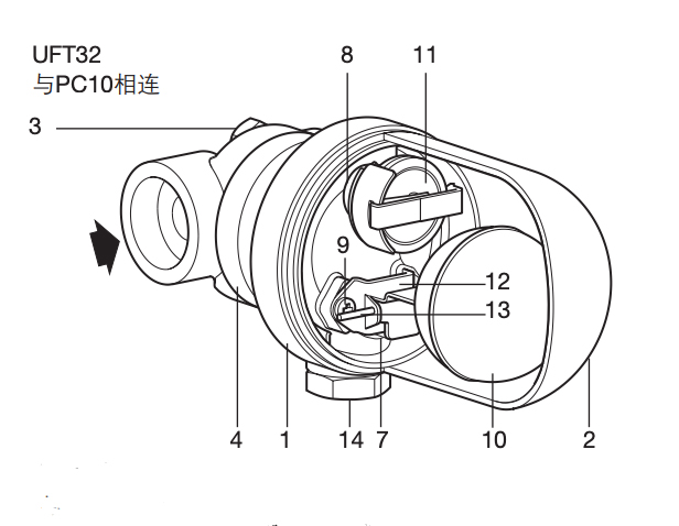
Ductile iron (SG iron) body for pressure service with a bolted cover that can be opened for inspection. The float and lever assembly drives a hardened stainless steel valve plug against a replaceable seat. The HC orifice gives a higher capacity than the standard FT14 at the same differential pressure, so smaller line sizes can carry larger loads.
Key features
- High discharge capacity for large condensate loads in a compact body
- Ductile iron body with bolted cover for in-line inspection
- Continuous, load-proportional discharge – no steam loss at part load
- Hardened stainless steel valve and seat for long orifice life
- Resistant to back pressure from lifted or pressurized condensate mains
- Interchangeable internals – one spare kit covers several sizes
Selection and sizing
Choose the FT14HC when the condensate load is high relative to the line size – for example a DN25 line carrying 1,500 kg/h of condensate at 10 bar g differential. Establish the load, the upstream pressure, the back pressure and the allowable lift, then check the capacity curve for the selected orifice at the minimum differential pressure the plant will see. Size on the minimum differential, never the maximum.
Installation and maintenance
Install with a strainer upstream, a sight glass downstream and a bypass for maintenance. Keep the trap at or below the drain point and give it a straight inlet. On large loads, fit an air vent at the top of the equipment to prevent air binding at start-up, which is the most common cause of a float trap appearing to fail.
Options and spare parts
Float and lever assemblies, seats, valve plugs and cover gaskets are available as spares. Insulation jackets and drain cocks can be supplied with the trap.